
Views: 0 Author: Site Editor Publish Time: 2026-10-10 Origin: Site


Underspecifying factory lifting equipment introduces severe operational risks, ranging from unplanned production downtime to severe safety hazards on the shop floor. Balancing maximum load requirements with high-frequency duty cycles and strict facility spatial constraints is a complex engineering task. You must achieve this mechanical balance without overspending on unnecessary features or compromising on mandatory safety mechanisms. We provide a technical, step-by-step framework below to help you evaluate, select, and plan the installation of a Wire Rope Hoist. This guarantees proper integration into your existing factory infrastructure. Proper upfront planning prevents costly structural modifications to your building later and guarantees long-term reliability for your daily material handling operations.
Accurate specification requires matching the standard lift distance and beam flange width before evaluating motor capacities or hoist classifications.
Wire rope selection (e.g., steel-cored, high tensile strength) must align strictly with the operational environment, load type, duty cycle, and relevant international standards.
Integrating a wire rope hoist for cranes demands strict adherence to safety braking standards and proper reel arrangement to mitigate premature wear and operational downtime.
You must calculate the maximum working load limit (WLL) accurately before looking at any equipment catalogs. Compare this absolute maximum against your average daily operational loads. Operating constantly at maximum capacity degrades mechanical components quickly. You should aim for a working load limit roughly 20% to 25% higher than your heaviest routine lift. This provides a necessary safety margin and extends the lifespan of your overhead industrial lifting equipment. Dynamic loading impacts hoist longevity significantly. Shock loads, such as pulling a stuck part from a casting mold or sudden jerky stops, multiply the effective load weight on the wire rope and gear train. You must account for these dynamic forces during the specification phase to prevent micro-fractures in the gear teeth.
Determining the appropriate hoist classification dictates how long the machine will survive in your facility. Use CMAA, FEM, or ISO standards for this evaluation. Base your decision on operational frequency, the specific load spectrum of your facility, and the maximum motor starts per hour. A light-duty classification fails within months in a heavy manufacturing environment because the motors overheat and the contactors weld shut. Conversely, specifying a severe-duty classification for occasional maintenance lifts wastes capital. You must match the classification to your actual production workflow.
CMAA Class | FEM Standard | ISO Standard | Max Starts/Hour | Typical Factory Application |
|---|---|---|---|---|
Class A/B | 1Bm / 1Am | M3 / M4 | Up to 150 | Infrequent maintenance, light assembly, standby operations. |
Class C | 2m | M5 | Up to 240 | Machine shops, general manufacturing, moderate usage. |
Class D | 3m | M6 | Up to 300 | Heavy machine shops, foundries, high-frequency lifting. |
Class E/F | 4m / 5m | M7 / M8 | Over 300 | Continuous bulk handling, severe duty, custom automated cycles. |
Measure the required standard lift distance carefully from the floor to the highest required hook position. Ensure the drum holds enough rope to equal or exceed your maximum required vertical travel without leaving less than two wraps on the drum. Calculate true headroom limitations within your factory layout. Headroom is the exact vertical distance from the beam's running surface to the saddle of the hook when fully raised. Tight vertical spaces require specialized low-headroom configurations where the hoist body sits parallel to the beam. Ignoring this dimension leads to incompatible equipment deliveries and the inability to lift parts over existing machinery.
You must also evaluate the existing beam specifications. Verify flange width compatibility before ordering any trolley. Check the track condition for wear, pitting, or deformation. Assess the structural integrity of the supporting framework. The building structure must safely support the dead weight of the hoist plus the maximum dynamic load. Assess approach dimensions thoroughly to evaluate hook coverage areas across the floor.
Measure the end approach: the distance from the center of the hook to the end of the runway beam.
Measure the side approach: the distance from the center of the hook to the centerline of the runway rail.
Identify dead zones where the hoist cannot reach due to building columns or HVAC ductwork.
Map these dimensions on your facility blueprints to guarantee full operational coverage.
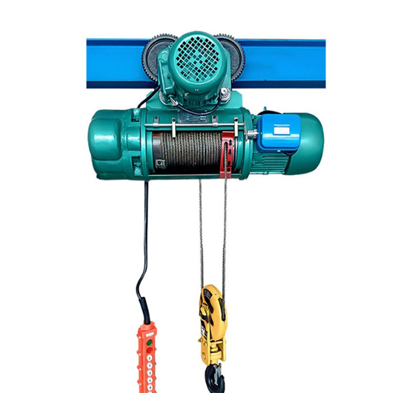
Specify variable frequency drives (VFD) for your lifting and travel motors. VFDs provide precision load control and enable micro-speed positioning for delicate assembly tasks, such as mating heavy engine blocks. VFDs reduce mechanical wear on the entire system by eliminating the harsh mechanical shocks associated with single-speed across-the-line motor starters. Smooth acceleration and deceleration protect the supporting structure from sway and impact loads. You should evaluate gear train durability closely. Look for AGMA-rated helical or herringbone gears. Enclosed oil-bath lubrication systems offer superior cooling and protect gears from factory dust and debris better than grease-packed gearboxes.
Analyze motor duty ratings before finalizing specifications. Look for motors designed specifically for crane duty, typically featuring Class F or Class H insulation to withstand high internal temperatures. Standard industrial motors cannot handle the frequent reversing and jogging required in material handling. Evaluate the cooling mechanisms of the industrial wire rope hoists. External ribbed aluminum housings and forced-air cooling fans improve heat dissipation during heavy use. Consider the benefits of modular drive designs. Modular systems allow you to replace a faulty motor or brake assembly without dismantling the entire gearbox, reducing production downtime during critical repairs.
Specify hardened steel trolley wheels for heavy applications. Wheels take the brunt of the abuse during travel. Design them to match your specific beam flange profile exactly. Flat-tread wheels fit wide-flange beams (W-beams). Tapered-tread wheels fit standard I-beams (S-beams). Running a flat wheel on a tapered beam destroys both the wheel and the beam flange within months. Specify wheels hardened to at least 400 Brinell to ensure they outlast the runway steel. You must evaluate the wheel bearings carefully. Lifetime-lubricated, double-row spherical roller bearings reduce maintenance overhead and handle both radial and thrust loads effectively.
Inspect the integration of guide rollers on the trolley frame. Guide rollers sit horizontally and roll against the edge of the beam flange. They ensure precise alignment along the beam and prevent binding during heavy-load traverses. Guide rollers eliminate wheel flange friction against the beam edge, which is the primary cause of premature wheel wear and metal shavings dropping onto the factory floor. This simple mechanical addition extends the lifespan of both the wheels and the structural beam significantly.
Define the material and construction requirements for the wire rope clearly. Specify an Independent Wire Rope Core (IWRC) rather than a fiber core when operating in high-temperature environments or when the rope spools in multiple layers on the drum. Fiber cores compress under heavy multi-layer spooling, causing the outer strands to rub and snap. High tensile strength requirements (typically 1960 N/mm2) depend on your load capacity and sheave diameters. Specify regular right-hand lay configurations and ensure they comply with ISO and ASME B30.16 standards. Proper construction prevents the rope from untwisting under load.
Understand the engineering importance of orderly reel arrangement. Deep-grooved drums are mandatory for proper spooling. The grooves guide the rope into neat layers, preventing overlapping during the lift. Overlapping causes severe crushing of the rope strands, leading to premature rope fatigue and catastrophic failure. Ensure the fleet angle between the drum groove and the lead sheave remains under 1.5 degrees to prevent the rope from climbing out of the grooves. A heavy-duty rope guide ring keeps the rope in the grooves and maintains tension even during slack rope conditions. You must inspect these cast-iron or composite guides regularly for wear.
Mandatory automatic safety brakes are non-negotiable. Design them to engage instantly during power failures. They must hold the load securely without slipping. DC disc brakes provide reliable, fast-acting performance and typically feature a 150% torque rating relative to the motor's full load torque. Adjusting the air gap on a DC disc brake is a routine maintenance task. As the brake pads wear down, the gap widens. If the gap exceeds the manufacturer's tolerance, the magnetic coil lacks the power to pull the pressure plate back, causing the brake to drag and burn out the motor. Specify hoists with external wear indicators to monitor this.
Integrate upper and lower limit switches into the control circuit. Geared upper limit switches prevent over-travel of the hook block. A secondary block-operated upper limit switch acts as a failsafe to stop block-two-block incidents entirely. A block-two-block event occurs when the hook block crashes into the hoist frame, snapping the wire rope instantly. Lower limit switches ensure at least two full wraps of rope remain on the drum at the lowest hook position. Electronic overload limiters protect the structural integrity by cutting power to the lifting motor if the load exceeds 110% of the rated capacity.
Identify use cases for low-headroom environments. Tight factory footprints require specialized equipment. Vertical space is often at a premium in older facilities or areas with low roof trusses. A compact electric hoist solves these spatial challenges by utilizing an offset drum design. It positions the drum parallel to the beam and uses a counterweight system to balance the load. This raises the hook block higher than standard configurations, allowing you to gain valuable inches of lifting height. Analyze the conceptual trade-offs carefully. A compact design footprint often restricts maintenance access. Technicians may struggle to reach internal contactors or adjust the brake air gap without removing the entire unit from the beam.
Consider integration requirements for different track systems. Monorail systems require specific trolley designs because they often navigate curves and switches. Single-girder applications handle straight-line transfers. The trolley must articulate slightly to handle monorail curves. Rigid trolleys bind and stall on curved tracks, damaging the wheel flanges. You must specify the exact turning radius of your beam to the manufacturer. This ensures they provide the correct trolley articulation and wheel spacing to navigate your specific track layout without binding.
Match the hoist frame to your existing bridge crane infrastructure. Choose between normal headroom, low headroom, or double girder trolleys. A wire rope hoist for cranes must integrate seamlessly with the bridge design. Double girder configurations sit on top of two parallel beams. They provide the maximum possible hook height and superior stability for high-capacity loads. Evaluate dual-motor trolley designs for these setups. Dual motors drive both sides of the trolley simultaneously. They ensure smoother travel along the bridge beam and prevent the trolley from skewing under heavy, off-center loads.
Determine your exact duty cycle requirements by logging actual lift frequencies over a standard shift.
Review historical maintenance logs of previous equipment to identify frequent failure points.
Upgrade to severe-duty mill-rated equipment if your operations run 24/7 or involve continuous bulk handling.
Specify flux vector drives for closed-loop control on heavy-duty cranes requiring millimeter precision.
Standard commercial hoists fail in continuous production environments. Severe-duty models feature thicker steel frames, larger gearboxes, and higher-rated contactors in the electrical panel. The initial capital investment is higher for mill-rated equipment. However, they withstand the abuse of continuous manufacturing schedules. You must evaluate your operational intensity honestly. Underestimating your needs leads to constant breakdowns, burned-out motors, and snapped ropes.
Specify NEMA or IP-rated enclosures for all electrical panels and motors. Factory environments expose equipment to severe conditions. Humid, dusty, or corrosive areas degrade standard components quickly. IP55 ratings protect against standard factory dust and low-pressure water jets. IP66 ratings offer superior protection for washdown environments or heavy particulate areas like foundries. You must protect the motors, brakes, and control boxes. In high-humidity environments, specify space heaters inside the motor windings. These heaters activate when the motor is off, preventing condensation from forming and shorting out the stator.
The impact of extreme ambient temperatures is significant. Cold environments increase gearbox lubrication viscosity, which strains the motor during startup and can blow seals. Hot environments accelerate wire rope fatigue and degrade the core lubrication of the rope. Select specialized coatings for harsh installations. Chemical-exposure installations demand two-part epoxy paint systems. Galvanized ropes resist rust in high-humidity zones. Stainless steel components prevent corrosion in food processing plants. You must specify these environmental protections during the planning phase because retrofitting weather protection is difficult and expensive.
Plan your erection logistics meticulously. Coordinate secondary lifting equipment for the installation day. You need mobile cranes, scissor lifts, or heavy-duty forklifts to raise the unit to the runway beam. Stage the equipment safely on the floor and perform all pre-wiring before lifting begins. Manage supply chain lead times for specialized components. Delays in receiving custom articulated trolleys halt the entire project. You must prepare the site before the equipment arrives. Clear the floor space beneath the installation zone and restrict personnel access during the overhead work.
Avoid common implementation pitfalls. Flange width mismatches are the most frequent error. If the trolley is too wide, it will fall off the beam. If it is too narrow, it won't mount. Use the manufacturer-provided spacer washers correctly to dial in the exact wheel spacing. Improper electrical supply phasing causes three-phase motors to run backward. This damages the rope guide immediately when the operator presses "Up" and the hook goes down, bypassing the limit switches. Conduct pre-installation structural surveys and perform comprehensive electrical audits to verify voltage drops under load.
Execute mandatory load testing protocols before putting the equipment into service. Commissioning checklists ensure compliance with OSHA and ASME safety standards. Test all limit switches without a load first. Perform a dynamic load test at 100% capacity, running the hoist through its full range of motion. Perform a static load test at 125% capacity, lifting the load just inches off the floor. Verify the brakes hold the overload without slipping. Document all test results for your safety records. Never skip the commissioning phase.
Compile your facility blueprints and measure your exact beam dimensions, including flange width and track turning radius.
Gather your historical load data and shift schedules to calculate your true duty cycle and required CMAA/FEM classification.
Document all environmental variables, including ambient temperature ranges, humidity levels, and airborne particulates in the operating zone.
Request a detailed, site-specific technical proposal from qualified hoist manufacturers based on your documented measurements and duty cycle data.
Schedule a structural audit of your existing runway beams with a licensed engineer before finalizing any heavy-duty equipment purchase.
A: Wire rope models handle heavier capacities, offer faster lifting speeds, and provide smoother operation for precise positioning. Chain hoists are typically used for lighter loads under five tons and operate at slower speeds. Wire rope systems are the standard for heavy-duty, high-frequency factory production.
A: Measure the exact bottom width of your I-beam or wide-flange beam using calipers. Measure the thickness of the flange edge. Check for any structural deformities, sweep, or wear along the runway. Provide these precise measurements to the manufacturer to ensure the trolley wheels fit perfectly.
A: The rope must feature high tensile strength steel wire, typically 1960 N/mm2. It requires an Independent Wire Rope Core (IWRC) for crush resistance on the drum. The construction must follow regular right-hand lay configurations and strictly comply with ASME B30.16 or ISO standards.
A: Operators must perform a basic functional test daily before use. Maintenance personnel should conduct a thorough mechanical inspection monthly, checking brake pad wear, air gap measurements, and spring tension. Annual load testing is mandatory to ensure the brakes hold capacity under power failure conditions.
A: Yes, but it requires a specialized top-running trolley frame. Compact models are typically designed for under-hung monorails. To retrofit a double-girder system, the manufacturer must engineer a custom crab trolley to ensure the compact drum aligns correctly between the two bridge beams.
A: Incorrect spooling usually results from a damaged rope guide or exceeding the maximum fleet angle. Pulling loads at an angle (side-pulling) forces the rope out of the drum grooves. Slack rope conditions also cause layers to cross. Always maintain vertical tension and replace worn guides immediately.


