
Views: 0 Author: Site Editor Publish Time: 2026-10-05 Origin: Site


Scaling material handling in high-demand industrial environments requires equipment that simply does not fail. When standard lifting mechanisms face high-capacity loads, continuous duty cycles, and strict load positioning demands, operational bottlenecks emerge. Facility managers quickly discover the physical limitations of basic lifting tools under these extreme conditions. You need an engineered solution built specifically for heavy-duty applications. The Wire Rope Hoist serves as this definitive industrial workhorse. This guide provides a technical framework for evaluating when and why to specify this equipment over standard alternatives. You will learn how to assess operational thresholds, compare mechanical advantages, and implement these complex systems safely. We will examine load distribution mechanics, duty cycle classifications, and the structural requirements necessary for proper facility integration.
Capacity and Duty Cycle Dominance: Wire rope hoists are structurally required for continuous, high-volume handling (typically above 5-10 tons) where chain hoists experience accelerated wear.
Precision and Speed: The grooved drum design of a wire rope hoist for cranes allows for faster lifting speeds, greater operational efficiency, and smoother, more precise load placement.
Versatility Across Demanding Environments: Engineered for high performance, these hoists are the preferred choice for rigorous applications in steel mills, machine shops, and fabricating plants.
Facility Integration: Proper specification requires evaluating headroom constraints, structural load-bearing capacity, and specific industry classification standards (CMAA/FEM/ISO).
Facility managers must recognize the physical limits of their current lifting infrastructure. Upgrading becomes necessary when daily loads consistently exceed the 10-ton mark. Continuous multi-shift operations also dictate a fundamental change in lifting mechanics. Standard equipment degrades rapidly when subjected to extreme temperatures or highly corrosive environments. Recognizing these operational triggers prevents catastrophic equipment failure on the factory floor. You must track the frequency of lifts per hour and the average load weight. When your facility operates near maximum capacity for extended periods, standard chain mechanisms stretch and deform. Upgrading to a robust wire system ensures continuous production without unexpected mechanical downtime. You also need to monitor the ambient operating temperatures. Standard motors overheat when pushed beyond their thermal limits during continuous cycling. Heavy-duty systems incorporate specialized cooling mechanisms to handle these exact scenarios.
Heavy machine shops require exact positioning for massive, expensive components. A machinist cannot risk dropping a 20-ton engine block due to equipment failure. Steel warehouses move long, awkward, and heavy loads continuously throughout the day. Fabricating plants handle abrasive materials that destroy standard lifting chains. Foundries operate in extreme heat that compromises basic steel tensile strength. These demanding environments require specialized lifting solutions. industrial wire rope hoists deliver the necessary durability for these rigorous applications. The equipment withstands the ambient dust, heat, and continuous strain inherent in heavy manufacturing. Engineers specify these systems because they maintain structural integrity under conditions that cause lesser equipment to fail. In a stamping plant, for example, pulling heavy dies requires smooth, controlled power that only a wire system can provide.
A wire rope hoist for cranes distributes weight across dozens of individual steel strands wrapped around a central core. This multi-strand design reduces point-stress significantly during heavy lifts. If a single outer wire breaks due to fatigue, the remaining strands continue to hold the load safely. This built-in redundancy enables the secure handling of oversized or highly asymmetrical loads. The rope flexes naturally as it spools, absorbing minor shock loads that would otherwise transfer directly to the crane bridge. This weight distribution mechanism protects both the load and the supporting structural steel from sudden dynamic forces. The core of the rope, whether fiber or independent wire, provides internal support to keep the outer strands perfectly positioned under massive radial pressure.
Baseline expectations for motorized lifting vary drastically by application. Light-duty assembly lines might survive using basic chain mechanisms for intermittent tasks. Heavy manufacturing requires an industrial electric hoist built specifically for continuous, grueling strain. You must evaluate the motor housing design, gear train durability, and the thermal capacity of the braking systems. Industrial models feature enclosed, fan-cooled motors that dissipate heat rapidly during continuous use. The gearboxes utilize helical cut gears running in an oil bath for maximum longevity. Differentiating between a commercial-grade tool and true industrial equipment ensures you specify the right machine for your production line. Look for motors with Class F or Class H insulation to guarantee they survive the high operating temperatures found in continuous-duty cycles.
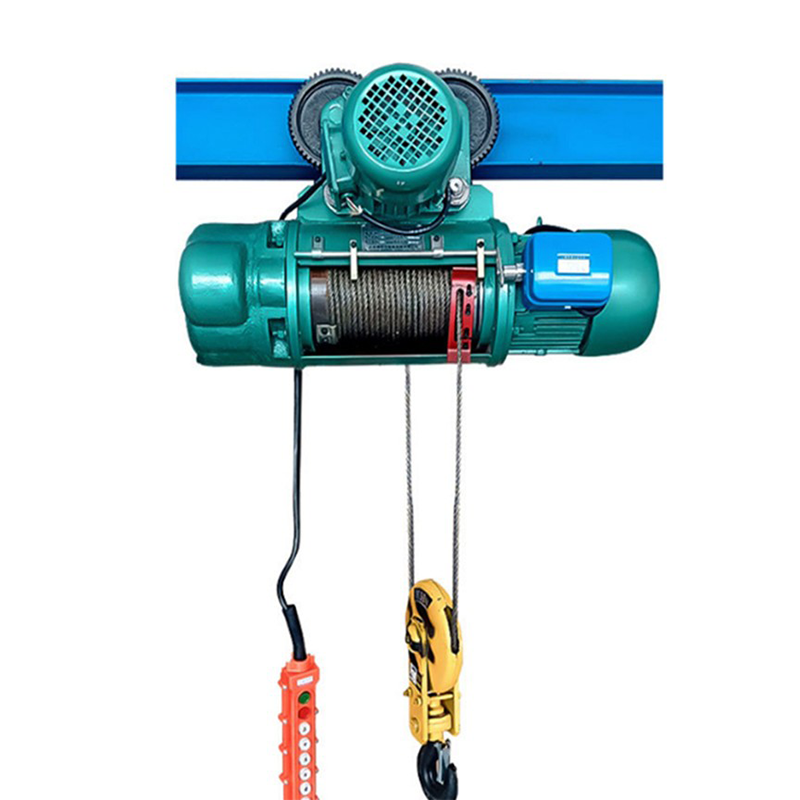
Wire rope utilizes a distinct structural design featuring a core surrounded by multiple twisted steel strands. Welded steel chains rely entirely on interlocking solid metal links. Chain links bear the entire load weight on two microscopic contact points where the links intersect. This creates massive friction and point-loading stress. Wire rope distributes the load along the entire length of the engaged rope and across hundreds of individual wires. This structural difference explains why wire rope handles massive capacities effortlessly. When a chain link fails, the entire system drops the load instantly. When wire rope fatigues, it shows visible signs of wear long before a catastrophic failure occurs. Inspectors can spot broken outer wires during routine checks and schedule a replacement without interrupting production unexpectedly.
Technical Parameter | Wire Rope Hoist | Electric Chain Hoist |
|---|---|---|
Optimal Capacity Range | 5 Tons to 80+ Tons | 1/8 Ton to 5 Tons |
Lifting Speed | High (Often exceeds 30 FPM) | Moderate (Typically under 16 FPM) |
Load Distribution | Dispersed across multiple strands | Concentrated at link contact points |
Operation Smoothness | Exceptionally smooth, true vertical lift | Subject to polygon effect (bouncing) |
Failure Mode | Gradual wire fraying (predictable) | Sudden link snap (unpredictable) |
Duty Cycle Suitability | Continuous, severe industrial duty | Intermittent to moderate duty |
Headroom Requirements | Can be optimized with low-headroom designs | Generally requires more vertical space |
The drum-and-rope configuration provides a distinct mechanical advantage for precision operations. Chain hoists suffer from a mechanical phenomenon known as the polygon effect. As the rigid chain links pass over the load sprocket, they create a slight bouncing or shuddering motion. This vibration transfers directly to the load. Wire rope spools smoothly onto a precisely grooved steel drum. This continuous winding eliminates bounce entirely, resulting in true vertical lift and significantly faster cycle times. Operators can place heavy dies into presses with millimeter precision. The smooth operation also reduces wear on the crane runway beams and supporting building columns. Faster lifting speeds directly translate to higher daily throughput in busy manufacturing facilities.
Harsh manufacturing environments test equipment limits daily. Abrasive dust from grinding operations wears down chain links rapidly at their contact points. Wire rope systems, when properly lubricated, resist this abrasive wear effectively. High-heat environments, such as foundries, can warp or weaken solid chain links over time. Wire rope maintains its structural integrity under extreme thermal stress due to its dispersed mass. Specialized wire ropes feature independent wire rope cores that resist crushing on the drum. This makes them highly durable in environments where heavy loads create massive radial pressure on the hoisting equipment. You can also specify galvanized ropes to combat severe moisture and chemical exposure in processing plants.
Matching operational needs with standard classifications prevents premature equipment failure. The Crane Manufacturers Association of America defines duty classes ranging from Class A to Class F. High-volume handling facilities require Class D or higher. The Federation Européenne de la Manutention uses a similar classification system based on load spectrum and daily operating hours. Under-specifying a hoist for a high-volume application leads to burned-out motors, melted brake linings, and snapped cables. You must calculate your average load weight, maximum load weight, and total lifts per hour to select the correct classification. A Class D hoist handles heavy loads frequently, while a Class F hoist operates continuously under severe conditions without stopping.
Reeving configurations dictate lift speed, capacity, and load stability. A 2-part single reeved drum offers standard performance for general lifting. A 4-part single reeved setup increases the lifting capacity but reduces the lifting speed proportionally. Double reeved drums provide true vertical lift by spooling two ropes simultaneously from opposite ends of the drum. This prevents the hook block from drifting laterally as the rope winds upward. Selecting the correct reeving pattern ensures the hoist performs efficiently for your specific application. Engineers must balance the need for high-speed lifting against the requirement for heavy load capacity. True vertical lift is mandatory when loading precision machine tools or handling hazardous materials.
Mandatory safety features protect both personnel and expensive facility equipment. Electronic overload protection prevents the hoist from lifting loads that exceed its rated capacity. Redundant emergency braking systems secure the load immediately if primary electrical power fails. Upper and lower limit switches prevent the hook block from crashing into the drum or hitting the factory floor. Advanced systems also include phase reversal protection to prevent the motor from running backward. Ensuring your equipment includes these compliance features minimizes workplace accidents and protects your operational infrastructure from severe mechanical damage. Geared limit switches offer precise control over the maximum hook travel distance, adding another layer of operational safety.
Restrictive ceiling clearances complicate overhead crane installation in older facilities. A compact electric hoist design solves this vertical space issue. Low-headroom configurations mount the hoist body parallel to the crane beam rather than hanging directly beneath it. The rope drum and motor sit on opposite sides of the beam flange, acting as a counterweight. This engineering approach maximizes hook height, allowing you to lift larger items in tight spaces. Facilities with low roofs can still achieve heavy-duty lifting capabilities without undertaking expensive structural roof modifications. The offset design keeps the hook block tucked tightly against the bottom of the bridge girder.
Heavy industrial lifting requires equipment that lasts decades, not months. The superior durability of wire systems reduces unexpected downtime significantly. Continuous operation without mechanical failure justifies the initial engineering specification. Wire rope mechanisms utilize high-strength alloy steels that resist metal fatigue under constant tension. The enclosed gearboxes prevent contamination from airborne factory debris. When you evaluate lifting equipment, you must look beyond the immediate installation. You are securing a long-term asset that will dictate your production capacity for years. Reliable lifting equipment ensures your assembly lines never stop due to a broken hoist. The heavy cast iron housings protect internal components from accidental impacts on the factory floor.
Wire rope systems require specific, disciplined maintenance protocols. Regular lubrication prevents internal friction between the individual steel strands. Technicians must inspect the rope visually for fraying, broken wires, or a condition known as bird-caging. Drum grooves require periodic wear analysis to ensure the rope continues to spool properly without overlapping. You must measure the rope diameter regularly using precision calipers. A reduction in diameter indicates core failure or excessive external wear. Following a strict preventative maintenance schedule ensures the equipment reaches its maximum engineered lifespan while maintaining complete operational safety. You should document every inspection to track the wear rate over time.
Clean the old grease and debris from the wire rope using a stiff wire brush.
Apply a specialized penetrating lubricant that reaches the inner core of the rope.
Inspect the rope guide for cracks, excessive wear, or missing tension springs.
Measure the rope diameter at three different points to check for core collapse.
Examine the drum grooves for sharp edges that could slice the outer wires.
Test the upper and lower limit switches without a load attached.
Modern lifting systems incorporate Variable Frequency Drives to optimize power consumption. VFDs control the motor speed precisely by altering the electrical frequency and voltage. This technology reduces the massive power spikes traditionally associated with starting a heavy lift. VFDs provide smooth acceleration and deceleration, which reduces mechanical shock across the entire crane structure. This smooth operation extends motor life and reduces wear on the mechanical brake pads. The brake only engages to hold the load after the VFD has brought the motor to a complete stop. This drive technology transforms a standard hoist into a highly efficient precision instrument. Operators can program specific acceleration ramps to match the fragility of the load.
Retrofitting a heavier hoist introduces significant structural risks to your building. You must conduct comprehensive engineering assessments for existing bridge cranes and runway beams. The supporting structure must handle the increased dynamic loading and potential deflection limits. A heavier hoist increases the dead weight on the crane bridge. Ignoring this engineering step risks catastrophic facility damage or runway beam collapse. You must consult with a structural engineer to verify that your building columns and foundations can support the upgraded equipment safely. Reinforcing the runway steel is often necessary before installation. The engineer will calculate the maximum wheel loads to ensure the existing rails will not crack under pressure.
Operators accustomed to chain hoists face a distinct learning curve. Chain hoists often tolerate minor side-pulling without immediate failure. Side-pulling a wire rope hoist severely damages the rope guide and grinds down the drum grooves. This practice can snap the rope guide instantly, disabling the hoist. Training programs must emphasize keeping the hoist perfectly plumb over the load center of gravity before initiating a lift. Operators must understand the mechanical differences and adapt their rigging practices accordingly. Proper training prevents expensive damage during the first weeks of operation. You should implement strict disciplinary measures for operators caught intentionally side-pulling loads across the factory floor.
Specific operational environments demand specialized mitigation strategies. Marine applications require galvanized ropes and marine-grade epoxy coatings to prevent rapid saltwater corrosion. Handling molten metal in foundries necessitates heat-shields, specialized wire rope cores, and high-temperature wiring insulation. Outdoor installations require weather covers and internal space heaters to prevent condensation inside the motor housing. Matching the equipment specifications exactly to the environmental hazards ensures safe, reliable operation. Failing to account for environmental factors leads to rapid equipment degradation and severe safety hazards. You must specify IP65-rated enclosures if the hoist operates in areas subjected to heavy washdowns or extreme dust.
Consult with a certified structural engineer to perform a comprehensive load assessment of your facility runways and building columns.
Calculate your exact daily lift frequency and average load weights to determine the required CMAA or FEM duty classification before ordering.
Implement a strict operator training program focused entirely on eliminating side-pulling and enforcing proper load centering techniques.
Establish a preventative maintenance schedule specifically for wire rope inspection, deep core lubrication, and drum groove wear analysis.
A: Standard industrial models typically range from 3 tons up to 80 tons. Custom-engineered built-up hoists can handle capacities exceeding 250 tons for specialized applications like power plants or heavy steel mills.
A: Steel mills, foundries, heavy fabricating plants, automotive assembly lines, and large machine shops benefit most. Their high-volume, continuous-duty operations and massive load requirements dictate the need for robust wire rope systems.
A: Replacement depends entirely on the duty cycle and inspection results. Ropes must be replaced when they meet rejection criteria, such as a specific number of broken wires per lay length, visible bird-caging, or significant diameter reduction.
A: Yes. Low-headroom configurations mount the hoist body parallel to the crane girder. This design moves the drum and motor to the sides of the beam, maximizing the available hook height in restrictive spaces.
A: Side-pulling forces the wire rope out of the machined drum grooves. This severely damages the mechanical rope guide, frays the steel strands, and can cause the rope to overlap and crush itself on the drum.
A: Wire rope hoists use multi-strand cables on a grooved drum, offering higher capacities, faster speeds, and smoother lifts. Chain hoists use interlocking links, which are better for lighter, intermittent lifts but suffer from bouncing during operation.
A: You determine the classification by calculating the average load weight, the maximum load weight, the number of lifts per hour, and the total operational hours per day. Match these metrics against standard CMAA or FEM charts.


