
Views: 0 Author: Site Editor Publish Time: 2026-09-30 Origin: Site


Modern manufacturing lines hit a hard wall when manual material handling meets high-throughput demands. You cannot balance strict ergonomic safety standards with aggressive production quotas using muscle power alone. Manual lifting creates micro-delays at every workstation. Improperly specified lifting equipment tires out workers and introduces severe bottlenecks in repetitive assembly operations. Moving parts from point A to point B is straightforward, but precise component mating requires mechanical intervention. Integrating an Electric Hoist directly impacts cycle times, part positioning accuracy, and overall facility throughput. Upgrading your overhead lifting strategy eliminates manual strain and optimizes floor space. We will break down how to evaluate hoist architecture, specify the correct duty cycles, and implement advanced control features to maximize assembly line efficiency.
Capacity Planning: Specifying an electric hoist with a capacity 25% higher than the maximum load reduces motor strain and extends equipment lifespan.
Precision and Control: Variable speed controls, coupled with ergonomic operator interfaces, eliminate physical strain while allowing for millimeter-accurate component mating.
Space Optimization: Low headroom designs are critical for maximizing usable hook travel in constrained assembly cells, preventing costly facility modifications.
Risk Mitigation: Advanced overload protection and strict adherence to duty cycle classifications prevent costly unplanned downtime and dangerous side-pulling.
Manual lifting degrades worker performance over a long shift. Operators experience increased physical fatigue as hours pass. This fatigue leads to slower cycle times and a higher risk of musculoskeletal injuries. Repetitive strain from handling heavy parts directly impacts your daily production quotas. When workers tire, their movement speed decreases. Assembly lines rely on predictable, repeatable cycle times. Any physical degradation in operator performance introduces immediate bottlenecks into the workflow. You cannot maintain a high-velocity assembly line when the physical limits of your workforce dictate the pace.
Positioning inefficiencies waste valuable production time. Operators often struggle to manually align heavy or awkward components. Mating two machined parts requires precise alignment. Manual handling lacks the stability needed for millimeter-accurate positioning. Workers spend excess time adjusting, lifting, and realigning components. These micro-delays compound across hundreds of cycles per shift. You lose significant throughput when operators fight the weight of a component instead of focusing on the assembly task. Think about aligning a 150-pound pump housing onto a base plate. Doing this by hand means two workers wrestling with the part, risking pinched fingers and damaged seals. Mechanical lifting eliminates this struggle entirely.
Operators lacking proper overhead support often resort to dragging loads across workstations. This practice damages expensive components and creates severe safety hazards. Dragging parts across the floor degrades surface finishes and compromises structural integrity. It also introduces unpredictable friction forces. These forces can cause sudden load shifts, endangering nearby personnel. Side-pulling with inadequate equipment stresses building infrastructure and lifting hardware beyond their designed limits. A vertical lift is the only safe way to handle heavy materials in a dense factory environment.
Using pneumatic or manual hoists in high-volume environments creates hidden costs. Assembly lines require sustained, consistent power delivery. Manual hoists demand physical exertion, defeating the purpose of ergonomic intervention. Pneumatic hoists rely on compressed air systems. These systems often experience pressure fluctuations during peak facility usage. Pressure drops lead to inconsistent lifting speeds and jerky movements. Electric alternatives provide the continuous, reliable power necessary for smooth and predictable assembly operations, ensuring that the lifting speed remains constant regardless of what other machines in the facility are doing.
This equipment serves as the standard for repetitive, vertical lifting in most assembly cells. The internal mechanism utilizes a motorized sprocket to pull a hardened steel link chain. This design provides exceptional durability for continuous daily use. It handles the rigorous demands of fast-paced manufacturing environments without faltering. The compact footprint allows for easy integration into existing workstation layouts, especially when mounted on jib cranes or enclosed track workstation cranes.
You will find this architecture best suited for workstations requiring rugged durability. It excels in applications involving loads typically under 5 tons. Engine assembly, heavy machinery manufacturing, and metal fabrication rely heavily on this design. The compact body allows operators to maneuver the unit easily within tight spaces. It provides reliable lifting power without obstructing the operator's line of sight, which is critical when guiding a component into a tight machining center.
Selecting appropriate IP (Ingress Protection) ratings matters for assembly environments. Facilities exposed to dust, metal shavings, or moisture require sealed enclosures. An industrial chain hoist with a high IP rating protects internal electrical components. This protection prevents short circuits and premature motor failure. Environmental resilience ensures consistent operation regardless of ambient facility conditions. If you are operating near a washdown station or a grinding cell, a fully enclosed motor housing is non-negotiable.
This design delivers true vertical lift capabilities. The chain drops straight down from the sprocket, preventing horizontal load shift during lifting. It also features lower maintenance complexity compared to wire rope alternatives. Chain links are easy to inspect for wear or deformation using a simple go/no-go gauge. Lubrication requirements are straightforward and quick to perform. This simplicity reduces scheduled maintenance downtime and keeps your assembly line moving.
This architecture relies on a grooved drum and steel wire rope mechanism. The motor turns the drum, winding the rope smoothly into the machined grooves. This engineering difference provides significantly smoother and quieter operation. The continuous support of the rope prevents the slight bumping sensation sometimes felt with chain links as they engage the sprocket. It offers exceptional stability for highly sensitive components that cannot tolerate vibration.
Heavy-duty assembly lines utilize this equipment for high-capacity applications. Automotive chassis marriage and aerospace component handling often require lifting 5 or more tons. These industries demand exceptionally smooth lifting to prevent load sway. Even minor sway can damage delicate parts or misalign massive assemblies. The wire rope design dampens vibrations, ensuring the load remains perfectly stable during transport. An electric wire rope hoist provides the exact control needed for these massive, sensitive loads.
The continuous support of the wire rope allows for faster lifting speeds. You can move heavy components over longer distances without sacrificing stability. The grooved drum ensures the rope winds evenly, preventing tangles or sudden drops. This speed and stability combination drastically reduces material transport time across large assembly bays. Faster transport directly translates to increased daily production output, especially in facilities with wide-span bridge cranes.
Specification Category | Industrial Chain Design | Wire Rope Design |
|---|---|---|
Lifting Media | Hardened steel link chain | Stranded steel wire rope |
Typical Capacity Range | 1/8 Ton up to 5 Tons | 5 Tons to 50+ Tons |
Operation Smoothness | Moderate (slight link articulation during sprocket engagement) | Exceptionally smooth (continuous drum winding) |
Maintenance Complexity | Low (visual inspection, simple surface lubrication) | High (requires drum groove checks, rope alignment, core lubrication) |
Best Assembly Use Case | Workstation cells, engine mating, localized jib cranes | Aerospace, large chassis assembly, wide-span bridge cranes |
Headroom Profile | Generally compact, excellent for tight vertical spaces | Requires more headroom due to drum size, unless specially configured |
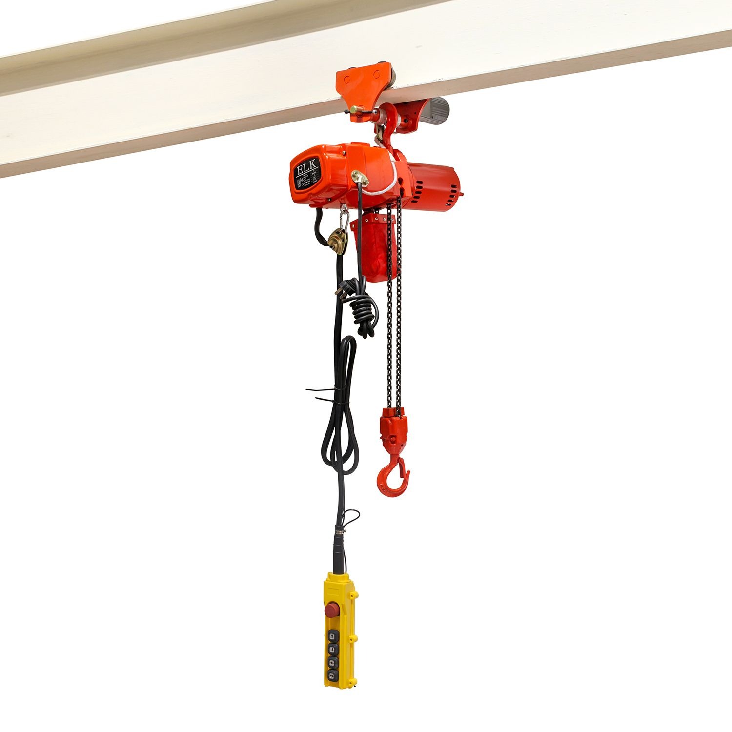
Dual-speed or Variable Frequency Drive (VFD) motors change how operators handle materials on the floor. They allow operators to move loads quickly across the cell to save time. Once the component nears its destination, the operator engages the creep speed. This ultra-slow movement creeps the load into exact alignment for assembly. VFDs provide seamless acceleration and deceleration, eliminating jerky movements that cause load swing.
Precise control directly prevents component collisions. When mating heavy parts, a sudden drop or swing can cause severe damage. Controlled deceleration allows the operator to stop the load exactly where needed. This accuracy reduces scrap rates and costly rework. Protecting expensive machined parts during assembly improves your overall yield and protects your profit margins. If you are dropping a transmission into a vehicle frame, you need millimeter accuracy. A single-speed motor will jerk the load, potentially damaging the mounting brackets. VFDs eliminate this risk entirely.
Traditional wired pendant stations tether the operator to the lifting equipment. The cable can tangle in machinery or obstruct the operator's movement. Wireless radio remote controls sever this physical connection. They provide complete freedom of movement around the assembly cell. Operators can position themselves optimally without fighting a cumbersome pendant cable.
Radio remotes allow operators to easily manipulate loads from the safest vantage point. They can step back to view the entire assembly or move close to monitor a tight clearance. This vantage point optimization speeds up component mating. Operators no longer rely on secondary spotters to confirm alignment. They control the lift while maintaining perfect visibility of the mating surfaces, which cuts down on communication errors and speeds up the entire operation.
Modern lifting equipment utilizes sophisticated mechanical and electronic safeguards. Slip clutches act as a mechanical barrier against excessive weight. If the load exceeds the rated capacity, the clutch slips, preventing the motor from lifting. Electronic load limiters monitor the current draw of the motor. They automatically halt operations if they detect a spike indicating an overload condition.
Overload protection serves as a strict efficiency tool. It actively prevents operators from lifting, lowering, or dragging loads beyond the rated capacity. This prevention avoids catastrophic motor failure and structural damage to your facility. Unplanned downtime from a burnt-out motor halts production entirely. Enforcing capacity limits through hardware ensures your assembly line remains operational and safe. You cannot rely on operators to guess the weight of a load; the equipment must enforce the limits automatically.
Low headroom configurations maximize usable hook travel. In this design, the hoist body is mounted parallel to the overhead beam rather than hanging directly below it. The lifting hook can retract much closer to the beam flange. This mechanical arrangement reclaims valuable vertical space within the assembly cell. It allows you to lift taller components without hitting the ceiling.
This design improves lifting efficiency in areas with low ceilings. Complex overhead infrastructure often restricts standard equipment installation. A low headroom industrial electric hoist fits into these constrained spaces easily. It prevents costly installation delays or the need for structural modifications to your building. You can optimize your existing floor plan without raising the roof, allowing you to handle larger assemblies in your current facility footprint.
Engineering reality dictates a strict rule of thumb for overhead lifting. You must select a capacity at least 25% higher than the heaviest anticipated load. If your heaviest engine block weighs 2,000 lbs, you specify a 2,500 lb unit. This margin accounts for the dynamic forces generated during lifting and stopping. It also accommodates the weight of any custom rigging or below-the-hook attachments.
This extra margin prevents the motor and braking system from operating at maximum stress. Running equipment at 100% capacity continuously generates excessive heat. Thermal overload degrades motor insulation and accelerates brake pad wear. The 25% buffer reduces this thermal stress significantly. It extends maintenance intervals and ensures your equipment survives years of rigorous assembly line use. Buying exactly to capacity is a false economy that will cost you in replacement parts and downtime.
Matching the equipment to your shift requirements is non-negotiable. ASME and CMAA define strict duty cycle classifications. An H2 rating suits light, infrequent lifts. An H3 rating handles general machine shop usage. An H4 rating is mandatory for high-volume, repetitive handling typical of automotive assembly. You must calculate the number of starts and stops per hour to determine the correct classification.
Purchasing a lower-rated unit offers initial cost savings. However, the operational reality quickly erases those savings. An H2 unit on an H4 assembly line will experience frequent thermal cut-offs. The internal sensors will shut down the motor to prevent melting. Your entire assembly line stops while the motor cools down. Specify the correct duty cycle to maintain continuous production.
H2 (Light Duty): Suitable for infrequent handling, maintenance tasks, or workstations where lifts occur only a few times per shift.
H3 (Standard Duty): Ideal for general machine shop fabrication, where lifts are distributed evenly but do not exceed 25% maximum run time per hour.
H4 (Heavy Duty): Required for high-volume assembly lines, steel handling, and foundries. Built for up to 50% maximum run time per hour with frequent starts and stops.
H5 (Severe Duty): Reserved for bulk handling or automated systems running near continuously.
You face an inherent trade-off between rapid material transport and delicate component mating. High-speed motors move parts across the factory floor quickly. However, they lack the finesse required to align a shaft into a bearing housing. Low-speed motors provide excellent accuracy but waste time during long vertical lifts. Balancing these metrics requires careful analysis of your specific assembly steps.
VFD solutions resolve this trade-off effectively. They provide both high-speed transport and ultra-low creep speeds in one package. However, specifying VFDs introduces higher initial capital expenditure. They also require cleaner electrical power to function correctly. Voltage spikes or harmonic distortion can damage VFD circuitry. You must ensure your facility's electrical grid can support these sensitive drives before installation.
Never install overhead lifting equipment without a comprehensive infrastructure audit. You must verify that existing I-beams, jib cranes, or workstation bridge cranes can handle the load. The structure must support both the static weight of the equipment and the dynamic forces of a loaded lift. Sudden stops multiply the force exerted on the beam. A structural engineer must certify the runway before installation.
Mismatched trolleys cause severe operational issues. The trolley wheels must perfectly match the taper and width of the beam flange. Incorrect sizing causes binding during horizontal travel. Operators will struggle to move the load across the workstation. It also causes uneven wear on the beam flange, eventually requiring costly steel replacement. Always specify trolleys designed specifically for your exact beam profile.
Your lifting equipment is only as efficient as its rigging. Standard hooks often fail to secure complex manufactured parts adequately. You must integrate custom spreaders, vacuum lifters, or mechanical manipulators. These below-the-hook devices must be specifically designed for the assembly task. They ensure the component remains balanced and oriented correctly for mating. For example, handling large sheets of metal requires a vacuum lifter to prevent bending, while long extrusions require a custom spreader bar to distribute the weight evenly.
Using improper rigging negates the speed advantages of modern electric hoists. If operators spend five minutes attaching slings to an awkward part, the fast lifting speed is irrelevant. Invest in quick-connect tooling and custom lifting jigs. Properly engineered rigging allows operators to secure and lift components in seconds, maintaining the rhythm of the assembly line.
Large manufacturing facilities often feature long electrical power runs. These long distances can cause significant voltage drops at the workstation. Low voltage forces the motor to draw more amperage to achieve the same lifting power. This excessive current leads to rapid motor overheating and premature failure. You must measure the voltage under load at the installation point. Upgrading from 230V to 460V 3-phase power often solves this issue by lowering the overall amperage draw, which keeps the motor running cooler during heavy use.
Most heavy-duty applications require stable 3-phase power. Single-phase power lacks the consistent torque delivery needed for smooth lifting. You must also protect against phase loss. If one phase drops out, the motor will stall and overheat instantly. Install phase monitoring relays to shut down the equipment safely if power quality degrades. Clean, consistent power is mandatory for reliable operation.
OSHA and ASME mandate strict inspection frequencies for overhead lifting equipment. You must perform daily visual checks before the first shift. Frequent inspections occur monthly, focusing on hook wear and chain lubrication. Periodic inspections require a complete teardown and load test annually. You must schedule these inspections to minimize disruption to your assembly schedule. Technicians must use calipers to measure chain wear across multiple links and feeler gauges to verify brake gap tolerances.
Standardizing models across your assembly line acts as a powerful mitigation strategy. Using the same brand and capacity reduces your spare parts inventory. Maintenance technicians only need to learn one mechanical system. This familiarity drastically reduces troubleshooting and repair time. Standardization transforms unpredictable breakdowns into manageable, brief maintenance interventions.
Common Issue | Potential Cause | Field Solution |
|---|---|---|
Motor overheating during shift | Exceeding duty cycle (e.g., using H2 hoist for H4 tasks) | Audit lift frequency; upgrade to higher duty cycle motor. |
Load drifting after stop | Worn brake pads or incorrect brake gap adjustment | Measure brake gap with feeler gauge; adjust or replace pads. |
Jerky lifting motion | Voltage drop or phase imbalance in power supply | Test voltage at the contactor under full load; correct wiring. |
Trolley binding on beam | Mismatched wheel taper or debris on beam flange | Verify wheel profile matches beam; clean runway surface. |
Chain popping or grinding | Lack of lubrication or worn load sprocket | Clean and lubricate chain; inspect sprocket for wear patterns. |
Conduct a comprehensive load and cycle-time audit of your current assembly bottlenecks to identify exactly where manual lifting slows production.
Consult with a structural engineer to verify your existing overhead beams can support the dynamic forces of motorized lifting equipment.
Specify equipment with a capacity at least 25% higher than your heaviest component to prevent thermal overload and extend motor life.
Invest in Variable Frequency Drives (VFDs) and radio remote controls to guarantee the millimeter-accurate positioning required for complex part mating.
Standardize your lifting hardware and custom below-the-hook rigging across the entire facility to streamline maintenance and reduce operator training time.
A: Chain designs use a motorized sprocket pulling a steel link chain, ideal for rugged, vertical lifts under 5 tons. Wire rope designs use a grooved drum and steel cable, offering exceptionally smooth, sway-free lifting for heavy-duty applications over 5 tons, such as aerospace or automotive chassis assembly.
A: Calculate the total weight of your heaviest component and add the weight of any custom rigging or below-the-hook lifters. Multiply that combined total by 1.25. This 25% safety margin prevents motor strain, accommodates dynamic lifting forces, and significantly extends the lifespan of the braking system.
A: No. They are designed strictly for vertical lifting. Dragging loads introduces severe horizontal stress, triggers overload protection systems, and damages the rope or chain guide. Side-pulling also creates dangerous unpredictable load swings, compromises building infrastructure, and immediately voids the manufacturer's warranty.
A: Yes, retrofitting is highly feasible. However, it requires a structural engineer to analyze the existing I-beams or jib cranes for dynamic load capacity. You must also ensure trolley wheel compatibility with the existing beam flange to prevent binding, uneven wear, and costly installation failures.
A: A low headroom configuration mounts the lifting body parallel to the beam, allowing the hook to retract much higher. This design reclaims valuable vertical space, enabling the installation of lifting equipment in tight spaces with restrictive ceiling heights and allowing clearance for taller assemblies.
A: The ASME/CMAA classifications define usage limits. H3 is designed for general machine shop use with moderate frequency. H4 is mandatory for high-volume, repetitive handling found in continuous assembly lines. Specifying H4 prevents thermal cut-offs and motor damage during demanding, multi-shift operations.
A: Core maintenance includes daily visual inspections, regular chain or wire rope lubrication, and verifying the functionality of upper and lower limit switches. Technicians must also periodically measure hook deformation, adjust brake gaps, inspect electrical contactors for pitting, and perform mandatory annual load testing.


