
Views: 0 Author: Site Editor Publish Time: 2026-10-07 Origin: Site


Operating in high-clearance environments like heavy manufacturing facilities, aerospace assembly hangars, and deep-shaft mining operations exposes the physical limits of standard lifting equipment. When vertical drops exceed 50 feet, traditional chain hoists fail. The deadweight of the chain creates massive operational bottlenecks. Chain containers reach maximum size limits, interfering with the load and surrounding infrastructure. Extreme heights also amplify pendulum effects, making load control dangerous. To overcome these barriers, facility engineers turn to specialized solutions. The Wire Rope Hoist stands as the engineered standard for high-lift applications. It manages extended vertical drops without the deadweight penalties of link chains. Reaching higher requires evaluating drum mechanics, reeving configurations, load capacities, and rope lay. These specific engineering choices ensure load stability, operational safety, and long-term mechanical efficiency.
Drum Spooling Overcomes Container Limits: Wire rope hoists utilize grooved drums to spool cable systematically, eliminating the bulk and deadweight restrictions of chain containers.
Reeving Configurations Dictate Stability: Advanced reeving (e.g., 4/1 or 4/2 setups) multiplies lifting capacity and controls the load's center of gravity during extended drops.
Rope Lay Impacts True Vertical Lift: Selecting the correct wire rope lay is critical at heights exceeding 70 feet to prevent rotational stress and load twisting.
Tension Management is Non-Negotiable: Achieving maximum service life at high lift heights requires strict adherence to winding tension protocols to prevent rope rolling and structural fatigue.
Lifting heavy loads over long vertical distances introduces complex physics. The primary engineering challenge involves managing a massive volume of steel cable without sacrificing overhead headroom or compromising the structural integrity of the lifting frame. Every component must work together to handle the dynamic forces generated during a 100-foot descent. You cannot simply add more cable to a standard hoist and expect it to perform safely at extreme heights.
The core of any high-lift system is the drum. Grooved hoist drums accommodate hundreds of feet of wire rope within a surprisingly compact footprint. The grooves guide the rope precisely, ensuring it wraps tightly and evenly without crossing over itself. This systematic spooling prevents tangles and reduces internal friction between the steel strands.
The relationship between the drum diameter and the rope diameter is known as the D/d ratio. This ratio directly dictates the maximum safe lift height and the longevity of the cable. A larger drum diameter reduces the bending stress exerted on the steel strands as they wrap around the curvature. When dealing with extreme heights, engineers often utilize multi-layer spooling. This requires specialized Lebus grooving to force the second and third layers of rope to sit perfectly in the valleys of the underlying layer. Proper multi-layer spooling prevents the upper layers from crushing the lower layers under the immense pressure of a fully suspended load. If the grooving is mismatched to the rope diameter, the cable will bind, leading to immediate structural damage.
Facilities often face the dual requirement of lifting massive capacities—ranging from 10 to 50 tons or more—across extreme vertical distances. This combination places extraordinary stress on the equipment. High-capacity hoists must distribute these massive loads evenly across the drum, the bearings, and the trolley frame to prevent catastrophic failure.
When the rope is fully extended to the floor, the entire weight of the load, plus the weight of the suspended cable, pulls down on the drum attachments. The hoist frame must maintain absolute structural integrity. Heavy-duty gearboxes and reinforced braking systems are integrated to hold these massive loads securely, preventing any downward slip when the motor stops. The braking torque must be calibrated to handle the kinetic energy of a heavy load moving at high speeds over a long distance.
Reeving refers to the specific method of wrapping the wire rope around multiple drums and sheave blocks. This configuration directly impacts the mechanical advantage, lifting speed, and load stability. Understanding reeving is essential for mastering high-lift operations. Different reeving setups provide distinct advantages depending on the required precision of the lift.
Common Reeving Configurations for High-Lift Applications | |||
Reeving Type | Configuration Description | Primary Advantage | Drawback at High Elevations |
|---|---|---|---|
2/1 Single Reeved | Rope anchored at one end, passes through one bottom sheave. | Fast lifting speeds, simple maintenance. | Noticeable hook drift as rope moves across the drum. |
4/1 Single Reeved | Rope passes through two bottom sheaves and one top sheave. | High lifting capacity, compact block design. | Increased hook drift; susceptible to load spinning. |
2/2 Double Reeved | Rope anchored at both ends, spools from center outward. | True vertical lift, zero lateral hook drift. | Requires a longer drum, consuming more headroom. |
4/2 Double Reeved | Combines double anchoring with multiple sheave passes. | Maximum capacity with true vertical stability. | Complex inspection process; heavy bottom block. |
A single-reeved system, such as a 2/1 or 4/1 configuration, anchors the rope at one end and wraps it through a bottom block. While a 4/1 setup provides excellent lifting capacity by distributing the load across four parts of rope, it causes the hook to drift laterally as the rope winds across the drum. In contrast, double-reeved configurations like 2/2 or 4/2 anchor the rope at both ends and spool from the center of the drum outward. This specific setup cancels out lateral movement. It minimizes hook drift, enhances positioning precision, and maintains a true vertical lift, which is mandatory when lowering a load over a long descent into a tight shaft or machinery housing.
When evaluating overhead industrial lifting equipment strictly through the lens of high-lift performance, the physical differences between chain and wire systems become starkly apparent. While chain hoists excel in localized, heavy-duty workstation environments, they face severe limitations as vertical distances increase. The physics of lifting simply favor wire rope at extreme heights.
The most significant barrier to using chain hoists for high lifts is deadweight accumulation. Link chains are heavy. At 50 or 100 feet of extension, the weight of the chain itself consumes a large portion of the hoist's total rated capacity. Steel wire rope offers a significantly lower weight-per-foot ratio. This allows the hoist to dedicate more of its motor power and structural capacity to lifting the actual payload rather than lifting its own lifting medium.
Chain hoists require chain bags or containers to catch the slack as the hook rises. For a 100-foot lift, the required chain bag becomes physically massive. These oversized containers create spatial limitations. They consume valuable headroom, interfere with the load, and can obstruct the hoist mechanics at extreme heights. Wire rope avoids this entirely by storing the slack neatly wrapped around the drum, keeping the lifting envelope clear of obstructions.
Cycle times dictate productivity in industrial operations. Wire rope hoists generally offer faster, smoother lifting speeds. When moving a load up and down a 60-foot shaft, a faster lifting speed drastically minimizes operational cycle times. You spend less time waiting for the hook to travel empty and more time moving actual product.
Smoothness is equally important. Chain links passing over a load sprocket create a polygonal effect, known as chordal action. This mechanical reality generates micro-vibrations that travel down the chain to the load. Wire rope, spooling continuously onto a round drum, provides inherent vibration dampening. This makes it the only viable choice for lifting sensitive equipment, aerospace components, or molten metal over long distances.
To maximize this smoothness, modern systems rely heavily on Variable Frequency Drives (VFDs). VFD integration is required for extended lifts. It allows operators to execute micro-positioning adjustments when the load is far away. VFDs provide programmable acceleration and deceleration curves. This prevents the load from bouncing or swaying like a pendulum over long vertical distances, giving the operator absolute control regardless of the drop height.
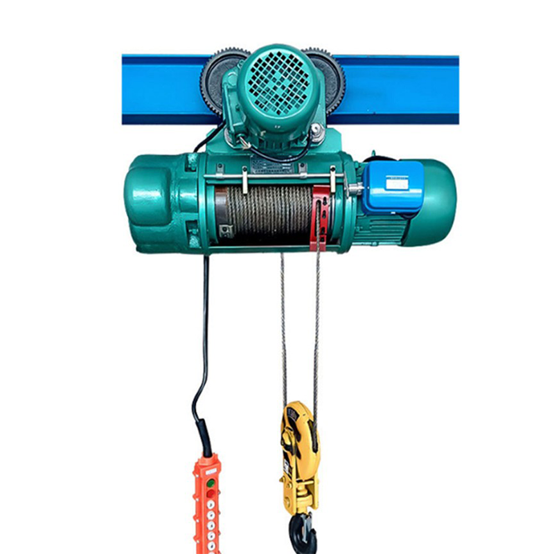
Matching a hoist to specific facility outcomes requires a deep evaluation of technical dimensions. You cannot order a hoist based on tonnage alone. High-lift applications demand specific configurations to prevent mechanical failure and ensure operator safety. Every component must be rated for the extended duration and unique stresses of a long vertical drop.
The term "lay" refers to the direction and manner in which the individual steel wires and strands are twisted together to form the rope. Regular lay ropes have wires twisted in one direction and strands twisted in the opposite direction, providing good crush resistance. Lang lay ropes have both wires and strands twisted in the same direction, offering superior flexibility and fatigue resistance over sheaves.
When vertical drops approach the 70-foot threshold, rotational dynamics change entirely. In a standard 4/1 reeving configuration, the natural tendency of the rope to untwist under load becomes highly problematic. The bottom block begins to spin, causing the multi-part lines to twist around each other. This twisting grinds the ropes together and can snap the cables. To eliminate this interference, engineers specify rotation-resistant or spin-resistant wire ropes. These specialized ropes feature multiple layers of strands wound in opposing directions. The inner layers counteract the rotational forces of the outer layers, keeping the load perfectly still during long lifts.
A continuous 100-foot lift places severe thermal demands on an industrial electric hoist motor. Lifting a heavy load for two straight minutes generates significantly more heat than a brief 20-foot lift. If the motor cannot dissipate this heat fast enough, the internal insulation will melt, leading to catastrophic motor burnout and dropped loads.
CMAA Hoist Duty Classifications for High-Lift Operations | |||
Duty Class | Service Level | Max On-Time (Min/Hr) | Suitability for High Lifts |
|---|---|---|---|
H3 | Standard / General | 15 minutes | Inadequate. Will overheat during repeated long drops. |
H4 | Heavy Duty | 30 minutes | Standard requirement for most 50+ foot lift applications. |
H5 | Severe Duty | Continuous | Required for automated systems or continuous deep-shaft mining. |
To prevent thermal failure, you must select the appropriate duty classification. The Crane Manufacturers Association of America (CMAA) and the Hoist Manufacturers Institute (HMI) define these ratings. For high-lift, high-frequency applications, standard H3 motors are insufficient. You must specify H4 or H5 classifications. These motors feature robust cooling fins, higher-rated insulation classes like Class F or Class H, and integrated thermal overload sensors that shut the system down before permanent damage occurs.
Operating lifting equipment at extreme elevations introduces harsh physical realities. The maintenance burden increases, and the margin for error shrinks. Facility managers must implement strict protocols to manage mechanical stress and protect their investment. Ignoring these realities leads to premature equipment failure and severe safety hazards.
During repeated long lifts, rotational stress gradually accumulates within the wire rope. Even with high-quality cables, the constant tension and release cycle forces the internal strands to shift. If left unchecked, this accumulated stress reaches a critical failure point, destroying the rope from the inside out.
The visible results of this stress are severe. The rope begins rolling in the sheaves, jumping out of the grooves and grinding against the sheave flanges. You might observe core protrusion, where the inner core pops out through the outer strands. In worst-case scenarios, bird-caging occurs, where the strands permanently separate and balloon outward. Mitigation requires proper break-in procedures when a new rope is installed on industrial wire rope hoists.
Install the new wire rope with constant, controlled back-tension to ensure tight initial drum wraps.
Run the hoist through 5 to 10 full-length cycles with absolutely no load attached.
Apply a light load (approximately 10% of rated capacity) and run 5 full-length cycles.
Gradually increase the load in 20% increments, running full cycles at each step until reaching maximum capacity.
Inspect the rope for any signs of twisting or improper seating in the drum grooves.
Winding wire rope onto the drum with sufficient tension is absolutely critical for extending its service life. A loose rope is a dangerous rope. When cable is spooled loosely, it creates soft spots on the drum. The layers do not support each other properly.
When a heavy load is subsequently applied, the tensioned upper layers of rope violently cut down into the loosely wound lower layers. This causes severe crushing, flattening the steel strands and destroying the structural integrity of the cable. Loose spooling also leads to erratic load bouncing, as the rope suddenly slips into gaps on the drum. Operators must ensure constant tension during installation and daily operation to maintain tight, uniform wraps. Using a tensioning stand during rope replacement is a mandatory practice.
The fleet angle is the geometric angle between the wire rope as it leaves the drum and the first sheave groove it enters. Managing this angle is a strict engineering requirement. Industry standards dictate that the fleet angle should generally not exceed 1.5 degrees for smooth drums and 2 degrees for grooved drums.
Excessive lift heights require wider drums to hold all the cable. If the distance between the wide drum and the first sheave is too short, the fleet angle becomes too steep. An improper fleet angle forces the rope to rub aggressively against the sheave flanges and the drum grooves. This friction causes accelerated wear, shaving metal off the rope and the equipment. Facility engineers must calculate these distances precisely during the design phase to keep the fleet angle within safe tolerances.
Inspecting 100+ feet of steel cable requires patience and strict adherence to safety protocols. Maintenance teams must visually and physically inspect the entire length of the extended-length rope. They look for broken wires, localized wear spots, valley breaks, and signs of core damage. Identifying a cluster of broken wires within one lay length dictates immediate replacement according to OSHA standards.
Lubrication is equally critical. The internal strands of a wire rope rub against each other continuously during long-drop operations. Without lubrication, this internal friction grinds the steel to dust from the inside out. Furthermore, equipment operating in harsh environments faces constant corrosion threats. Automated lubrication systems or rigorous manual greasing schedules are necessary to penetrate the outer strands and protect the rope core. Surface grease is not enough; the lubricant must flow into the valleys between the strands.
Purchasing a high-lift hoist involves balancing complex physical trade-offs. You must align the physical dimensions of the equipment with the architectural realities of your building while ensuring the mechanical specifications meet your production goals. A mismatch here results in equipment that either cannot lift the required height or physically crashes into your building's infrastructure.
There is a direct physical trade-off between the size of a high-capacity drum and the available headroom in your facility. To achieve a 100-foot lift, you need a large drum. A large drum requires a larger hoist frame. If your facility has low ceilings or tight clearances above the crane runway, fitting this massive equipment becomes a major engineering challenge.
Buyers must evaluate different hoist geometries. Low-headroom wire rope hoist designs position the drum and motor parallel to the crane girder, tucking the equipment up tight to maximize the hook's upward travel. Standard headroom, top-running configurations sit entirely on top of the bridge beams. While top-running designs are easier to maintain and generally accommodate larger drums for higher lifts, they require significant clearance between the top of the crane and the roof trusses. You must measure your exact vertical envelope before specifying the drum size for a wire rope hoist for cranes.
Take the following actionable steps when planning your next high-lift installation:
Calculate your exact maximum vertical drop to determine the necessary drum capacity and D/d ratio before contacting a manufacturer.
Specify a 4/2 double-reeved configuration if true vertical lift and zero hook drift are required for your precision operations.
Select rotation-resistant wire rope for any lifting application exceeding 70 feet to prevent block spinning and cable tangling.
Upgrade to an H4 or H5 motor duty classification to handle the extended thermal loads of continuous high-lift cycles without burning out.
Implement a strict daily tensioning and lubrication schedule to protect the wire rope from internal friction and core degradation.
A: Standard chain hoists are unviable for 100-foot lifts due to the immense deadweight of the chain itself, which drastically reduces the usable lifting capacity. Additionally, the required chain storage bags become physically massive, consuming valuable headroom and potentially interfering with the load or surrounding infrastructure.
A: A 4/2 reeving configuration anchors the rope at both ends and spools from the center of the drum outward. This setup cancels out lateral forces, eliminating hook drift and providing a true vertical lift, which is critical for precise load placement during long descents.
A: Standard rope lay naturally untwists under heavy loads, causing the bottom block to spin and the multi-part lines to tangle. At heights over 70 feet, rotation-resistant ropes with opposing strand layers are required to counteract these rotational forces and keep the load stable.
A: Loose spooling creates soft spots on the drum. When a heavy load is applied, the tensioned upper layers of rope violently cut down into the loosely wound lower layers, crushing the steel strands and permanently destroying the rope's structural integrity.
A: Lifting loads over long distances requires the motor to run continuously for extended periods, generating significant heat. High-lift hoists require H4 or H5 duty classifications, which feature better insulation and cooling mechanisms to prevent the motor from burning out under prolonged thermal stress.
A: The fleet angle is the geometric angle between the wire rope leaving the drum and the first sheave groove. If the angle exceeds 2 degrees due to a wide drum and short distance, the rope rubs aggressively against the sheave flanges, causing rapid, dangerous wear to both the cable and the equipment.


